3-DOF Spring-Loaded Robotic Finger
Designed, mathematically modeled, simulated, and experimentally validated a three degree-of-freedom spring-loaded robotic finger.
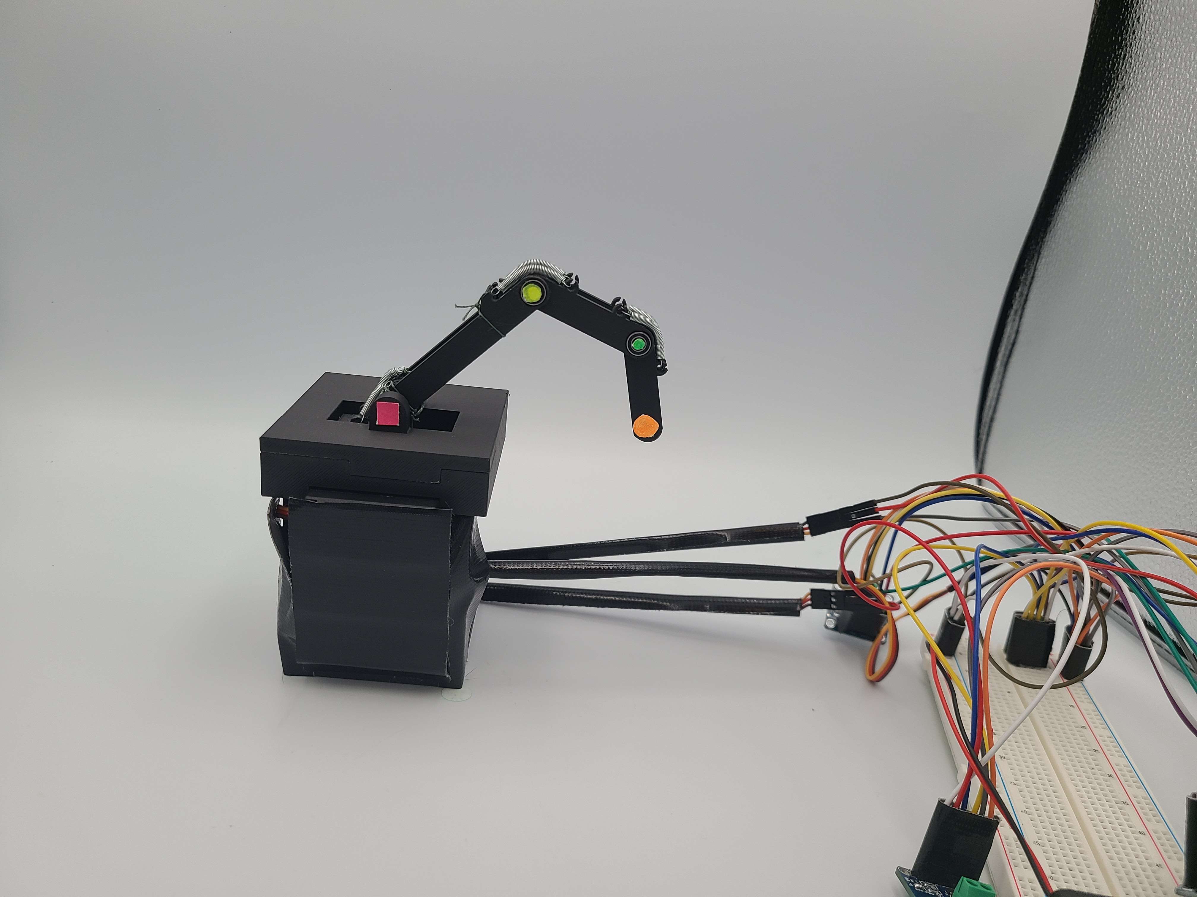
[Hardware Prototype with Colored Dots for Joint Tracking]
Team project (MXET 375 — Applied Dynamic Systems).
Motivation
This project was designed to replicate the motion of a human finger using a servo-driven flexion, and spring-return extension. The real life design was then rigorously validated against a mathematical model of its dynamics The goal was to bridge the gap between theoretical dynamic modeling (rotational inertia, torque-current relationships, spring forces) and the messier reality of a physical prototype.
Design & Modeling
The finger consists of three rigid 3D-printed phalanges (proximal, medial, distal) connected by revolute joints. Each joint is driven by an MG996R high-torque servo and returned to its rest position by a pair of springs, giving independent control of all three DOF.
To isolate each joint's motion from the rest, the tendons were routed through the center of each joint lower than the one they intended to affect. This resulted in approximately 0 torque around each joint from the tendons other than the designated flexion tendon for that joint.
We derived the full rotational equations of motion for each segment, accounting for:
- Rotational inertia of each phalanx
- Applied servo torque (estimated from a torque-current proportionality)
- Spring restoring torque at each joint
- Gravitational torque on each segment
- Viscous damping and friction
- Coupling forces between segments (reaction forces at each joint)
The system was simulated in MATLAB Simulink and Simscape Multibody, with recorded servo current data used as the torque input.
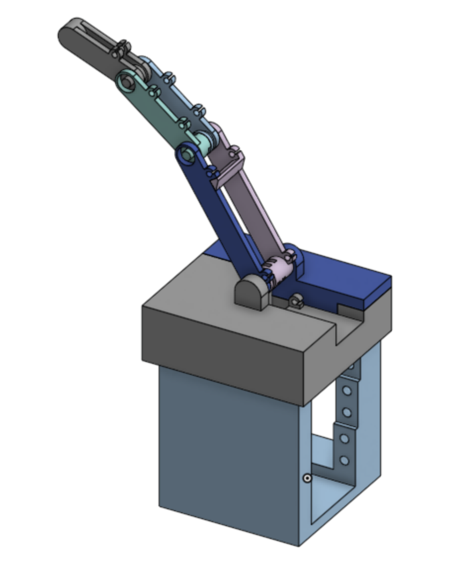
[Finger Assembly in Onshape]
Experimental Validation
Colored tracking markers were placed at each joint and a camera recorded the finger's motion. Joint angles were extracted from video using Python (NumPy and Pandas), then compared against the Simulink simulation.
The comparison revealed that simulated angles were smoother and lower-amplitude than experimental data. The physical system exhibited larger oscillations across all three joints. Key sources of error included:
- Servo current noise: servos have inherent noise from internal position sensing, contaminating the torque estimate
- Unmodeled dynamics: uneven spring compression, 3D-printed part deformation under load
- Joint friction that was difficult to characterize precisely
The biggest takeaway was the choice of actuator: BLDC motors would have provided a cleaner current signal for torque estimation, or a pre or post processing filter such as a bandpass on the servo current data could have improved the simulation input significantly.
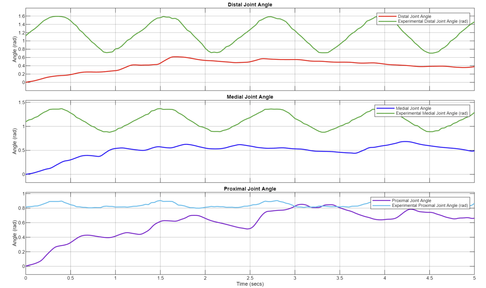
[Comparison of Experimental vs. Hardware Results]
Outcome
The project produced a fully functional spring-loaded finger prototype with independent 3-DOF actuation, a complete set of derived equations of motion, a validated Simulink model, and quantitative comparison between simulated and experimental joint trajectories. It reinforced core dynamics concepts such as rotational inertia, torque-current relationships, and spring-mass-damper behavior, while highlighting the practical challenges of translating theoretical dynamics into real hardware.